The method can be used for the production of metal wire. The method includes forming a metal foil, cutting the specified foil to form at least one core wire, and a profile of the specified conductor wire to give it the required configuration and cross-sectional dimensions. The method is particularly suitable for the production of copper wire, in particular a copper wire with a small diameter (eg approx. 0,005-0,5 mm), is achieved by simplifying the method and reducing costs. 19 Cp f crystals, 20 ill.
This invention relates to a method of making a wire. More specifically, this invention relates to a method of making wire through the phases of forming the metal foil, then cutting the foil into one or more wires, and living profiling to give the wire the desired shape and cross-sectional size. This invention is particularly suitable for the production of copper wire.
Background of the procedure
The usual method of manufacturing copper wire involves the following steps. Electrolyte swords roll to get the configuration of the rod. The rod is then cold worked through the draw die, which successively reduces the diameter and increases the length of the wire. In a typical manufacturing process, the manufacturing rods pour molten electrolytic copper into the rod, having a substantially trapezoidal cross-section, rounded edges, and a cross-sectional area of about 45,16 cm2; this block is in its preliminary stage to align the corners, after which it is passed through 12 stands of a rolling mill, of which it published in the form of a copper wire with a diameter of 7,94 mm, then the diameter of the copper wire to the desired size of the wire reduced by passing the rod through a standard round drawing die. Typically, these reduce the diameter that occurs in successive machines with the final stage of annealing, and in some cases are performed with intermediate annealing stages to reduce the processed wire.
The usual method for producing copper wire requires a considerable amount of energy and higher labor and material costs. The operation of melting, casting and hot rolling is exposed to the oxidation product and the potential is roll rolls, which can cause problems when drawing wire, mainly in the form of wire breaks.
Due to the advantages of the method according to the invention, the metal wire is simplified compared to the prior art and produced more cheaply. In a variant embodiment of the invention in the process according to the invention granulated copper, copper oxide or recycled copper are used as raw materials, this process does not require the use of the prior art stages comprising a first production of copper cathodes, followed by melting, casting and hot rolling cathodes to create a reserve of copper rods.
A short description of the procedure
This invention relates to a method of making a metal wire comprising: (a) forming a metal foil; (B) cutting the foil to form at least one core wire; and (C) profiling strands of wire to produce wire of the required size and configuration section. This invention is particularly suitable for the production of copper wire, in particular copper wire with a very small or extremely small diameter, for example the> In the accompanying drawings the same parts and characters are identified by the same numerals.
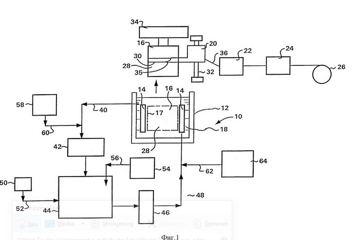
Figure 1 is a flow chart illustrating an alternative embodiment of the invention in which copper is deposited in the form of a galvanic protection on the vertically disposed cathode, forms a copper foil, and then slit the foil and in the form of copper wire strands of the cathode is removed, whereupon the copper wire is profiled to give a copper wire the required shape and dimension of the cross section;
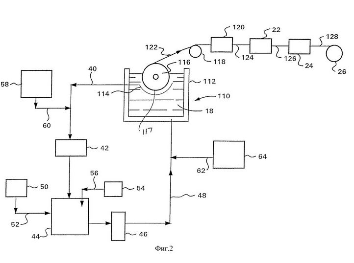
FIG. 2 illustrates a process flow illustrating another embodiment of the invention in which copper is deposited in the form of galvanic protection on the horizontally disposed cathode to form a copper foil which is removed from the cathode to form one or more. FIG Wire copper wire is cut, whereupon the strands of the copper wire are profiled to produce the required shape and dimension of the cross section of the copper wire;
Production of nickel wire and copper wire thinner than 0,5mm
Production of nickel wire and copper wire thinner than 0,5mm
Production of nickel wire and copper wire thinner than 0,5mm
Production of nickel wire and copper wire thinner than 0,5mm
Production of nickel wire and copper wire thinner than 0,5mm
Production of nickel wire and copper wire thinner than 0,5mm
Production of nickel wire and copper wire thinner than 0,5mm
Production of nickel wire and copper wire thinner than 0,5mm
Production of nickel wire and copper wire thinner than 0,5mm
Production of nickel wire and copper wire thinner than 0,5mm
Production of nickel wire and copper wire thinner than 0,5mm
Production of nickel wire and copper wire thinner than 0,5mm
Production of nickel wire and copper wire thinner than 0,5mm
Production of nickel wire and copper wire thinner than 0,5mm
Production of nickel wire and copper wire thinner than 0,5mm
Production of nickel wire and copper wire thinner than 0,5mm
Production of nickel wire and copper wire thinner than 0,5mm
Production of nickel wire and copper wire thinner than 0,5mm
Production of nickel wire and copper wire thinner than 0,5mm
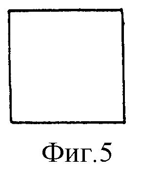
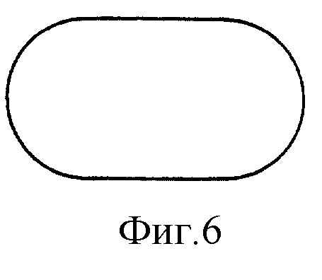
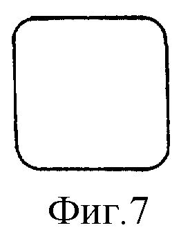
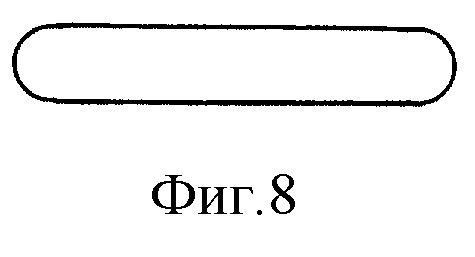
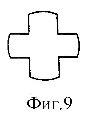
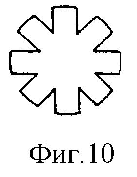
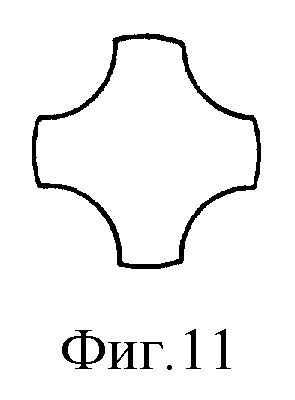
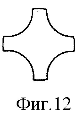
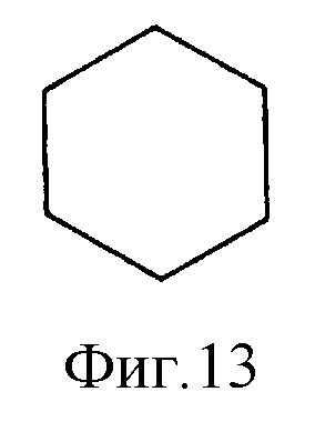
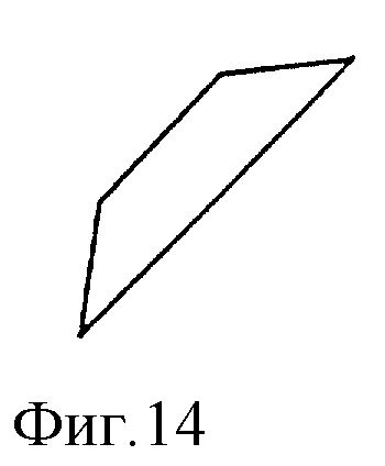
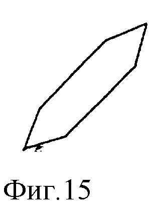
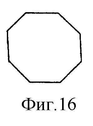
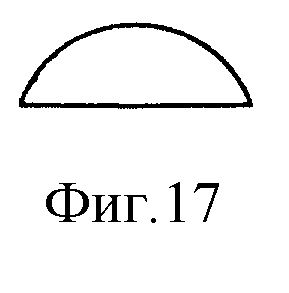
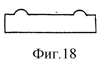
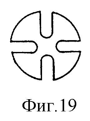
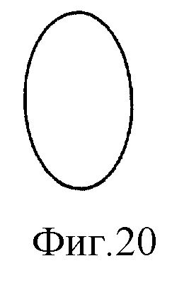
Fig. 3-20 shows the shape of the cross sections of wire made according to the invention.
Description of the preferred embodiments of the process
Wire produced by the method after sobrecaliente foil. Examples of such metals are copper, gold, silver, tin, chromium, zinc, nickel, platinum, palladium, iron, aluminum, steel, lead, brass, bronze and alloys of these metals. Examples of such alloys are alloys of copper with zinc, copper and silver, copper with tin and zinc, copper and phosphorus, chromium-molybdenum, nickel-chromium, nickel-phosphorus, etc., copper and alloys of copper are particularly preferred.
The metal foil is manufactured by one or two techniques. Forged or rolled metal foil that mechanically reduces the thickness of the metal strips or bars during the process, such as rolling. The coated film is produced by electrolytic deposition of metal on the cathode drum and subsequent detachment of the coated tape from the cathode.
Metal foil typically has a nominal thickness in the range from about 0,005 mm to 0,5 mm, and in a variant embodiment of the invention from about 0,10 mm to 0,36 mm, the thickness of the copper foil is sometimes expressed in terms of weight. Weight for foil according to the present invention, the values of the weight or the thickness are approximately within fid> 2: copper foil, which is the galvanic covering, is particularly preferred.
In a variant embodiment of the invention, the galvanic copper foil passes into the galvanically shaped well, which is equipped with a cathode and an anode. The cathode can be installed vertically or horizontally and is in the form of a cylindrical core. The anode is near the cathode and has a curved configuration, repeat the configuration of the cathode to create a uniform gap between the anode and cathode. The cathode to anode distance is generally about 0,3 to 2 cm. In one variant of the invention, the insoluble anode, it is made of lead, a lead alloy or titanium coated with a platinum group metal (such as Pt, Pd, Ir, EN) or their Oxides are coated. The cathode has a smooth surface for receiving the electrodeposited copper, and the surface, in a variant embodiment of the invention, is made of stainless steel, stainless steel, chrome or titanium.
In a variant of the embodiment of the invention, the galvanic covering of the copper foil is formed on a horizontally mounted rotating cylindrical cathode and then the lived copper wire is peeled off, and then strands of copper wire are profiled to obtain the desired shape and cross-sectional size.
In a variant of the invention, the electrodeposited copper foil is deposited on a vertically mounted cathode and forms a thin cylindrical copper jacket around the cathode. This cylindrical copper sheath is slit to form a thin copper wire strand that separates from the cathode and is then profiled to obtain the desired shape and cross-sectional size.
In a variant of the embodiment of the invention, the solution of the copper electrolyte flows between anode and cathode, and an electric current is applied for applying an effective voltage between anode and cathode for the deposition of copper on the cathode. The electrical current may be DC or AC with a DC offset. The flow rate of the electrolyte through the gap between anode and cathode is generally in the range of about 0,2 to 5 m / s, and in a variant embodiment of the invention from about 1 to 3 m / sec. The electrolyte solution has a concentration of pure sulfuric acid, generally, for example, in the range from 70 to 1 iwantlatina tub, in general, is approximately in the range of 25 to 100oC, and in a variant embodiment of the invention from about 40 to 70oC. The concentration of copper ions generally ranges from about 40 to 150 g / L and in a variant embodiment of the invention from about 70 to 130 g / L and in a variant embodiment of the invention from about 90 to 110 g / L. The concentration of ions in the net chloride is generally about 330 ppm, and in one variant embodiment of the invention to about 150 ppm, and in a variant embodiment of the invention to about 100 ppm. In a variant embodiment of the invention, the pure chloride ion concentration of about 20 ppm, and in one variant embodiment of the invention, up to about 10 ppm, and in one variant embodiment of the invention, up to about 5 ppm, and in a variant embodiment of the invention, up to about 2 ppm, and in a variant embodiment of the invention, to about 1 particles per million. In a variant embodiment of the invention, the ion concentration of pure chloride is less than about 0,5 ppm or less than about 0,2 ppm or less than about 0,1 ppm or less than about 0,1 ppm and in scrap not more than about 20 g / L, and typically not more than about 10 g / l current density generally about 538 to about 32280 a / m2 in a variant embodiment of the invention from about 4304 to 19368 a / m2.
In a variant embodiment of the invention, copper is released in the electrodeposition using a vertically installed cathode rotating at a peripheral speed of up to about 400 m / s, and in a variant embodiment of the invention from about 10 to 175 m / s, and in a variant embodiment of the invention from about 50 to 75 m / s, and in a variant embodiment of the invention from about 60 to 70 m / sec. In a variant embodiment of the invention, the upward flow of the electrolyte solution between vertically mounted anode and cathode is at a rate in the range of about 0,1 to 10 m / s and in one variant embodiment of the invention about 1 to 4 m / s and in a variant embodiment of the invention about 2 to 3 m / sec.
In the electrolytic deposition of copper, the electrolyte solution can optionally contain one or more active sulfur-containing materials. The term “active sulfur-containing MaterialScience, which is linked to the carbon atom together with one or more nitrogen atoms, also directly to the carbon atom. In this group of compounds the double bond may be present in some cases or alternate between a sulfur atom or a nitrogen and a carbon atom. The thiocarbamide is a suitable substance containing active sulfur. Suitable thiocarbamide, with a nuclear or isothiocyanate relationship S = C = N-. Also suitable for thiosinamine (alliteration) and thiosemicarbazide. Substances containing active sulfur must be soluble in the electrolyte solution and are compatible with other components. The concentration of the active sulfur-containing substances in the electrolyte solution during the electrolytic deposition in a variant embodiment of the invention is preferably about 20 ppm and in a range from about 0,1 to 15 ppm.
The copper electrolyte solution may also optionally contain one or more gelatins. Gelatine are heterogeneous mixtures of water-soluble proteins from collagen. The preferred gelatin is Kostany glue because it is relatively cheap, commercially available and easy to handle. The gelatin concentration in the electrolyte solution is generally in a variant embodiment of the invention in the range of about 0,2 to 10 parts per million.
The copper electrolyte solution may optionally also contain other additives known in the art to control the properties of the electrolytically coated film. Examples are saccharin, caffeine, molasses, guar gum, gum arabic, polyalkylene glycols (eg, polyethylene glycol, polypropylene glycol, polyisopropylene, etc.), dithiothreitol, amino acids (eg, proline, hydroxyproline, cystine, etc.), acrylamide, sulfopropyl, tetraethylene glycol, benzyl chloride, epichlorohydrin, chloroperoxybenzoic acid , Alkylene oxide (eg, ethylene oxide, propylene oxide, etc.), sulfoalkylation, thiocarbanilide, selenic acid, or a mixture of two or more of these components. In one embodiment of the invention, these additives are used in concentrations of up to about 20 parts per thousand and in one embodiment of the invention up to about 10 parts per thousand.
In a variant embodying the invention, the copper electrolyte solution contains no organic additives.
In the electrolytic deposition of copper, it is preferable to keep the ratio of the applied current density (I) to current density, Granello, at the level of 0,3. That is, I / she should preferably be about 0,4 or less, and in one variation, the embodiment of the invention is about 0,3 or less. The applied current density (I) represents the number of amps applied per unit area of the electrode. The current density is limited by diffusion (IL), which is the maximum density that copper deposition can be. The maximum deposition rate is limited by the rate at which copper ions can diffuse to the cathode surface and replace the previously deposited ions. This can be calculated using the following equation
The symbols used in this equation and their values are described below:
characters
I The current density A / cm2
IL The current density is limited by diffusion - A / cm2
n is synonymous with charge - equivalent / mole
F Faraday's constant - 96487 ASEK / equivalent
C The volume concentration of copper ions - moles / cm3
D the diffusion coefficient cm2 / s
The thickness of the concentrated boundary layer - cm
t is the number of transfer copper - infinitesimal value
The thickness of the boundary layer is a function of the viscosity, the diffusion coefficient and the speed of the CSOs for the deposition of copper foil:
The parameter - value of
I (A / cm2) - 1,0
n (equals / mol) - 2
D (cm2 / s) - 3.510-5
C (mol / cm3), Cu + 2 (CuS04) - 1,4910-3
Temperature (C) - 60
Pure sulfuric acid (g / l) - 90
Kinematic viscosity (cm2 / s) - 0,0159
Flow rate (cm / sec) - 200
In a variant embodiment of the invention, a rotating cathode is applied, and a copper foil is pulled off the cathode as it rotates. The film is cut with one or more cutting steps to form many living or copper strips of approximately rectangular cross-section. In one variant, the embodiment of the invention uses two consecutive stages of cutting. In one embodiment of the invention, the film has a thickness in the range of about 0,025 to 1,27 mm or from about 0,102 to 0,254 mm. The film is cut into strands with a width of about 6,35 to 25,4 mm or from about 7,62 to 17,78 mm or about 12,7 mm. These wires are then cut to a width that is 1 to 3 times the film thickness, and in a variant embodiment of the invention, the width to thickness ratio is from about 1,5: 1 to 2: 1. In a Varetsa before shooting section, which lived about 0,2 x 0,3 mm, then rolled or stretched to obtain wires with the required configuration and cross-sectional sizes.
In a variant embodiment of the invention, the electrolytic deposition of copper on a rotating cathode is in the form of a cylindrical core until the thickness of the copper on the cathode reaches about 0,127 to 1,27 mm or about 0,254 to 0,763 mm or about 0,508 mm. The slitter is used to cut copper on a thin copper wire, which is then peeled from the cathode. The slitter moves along the length of the cathode during rotation of the cathode. Slitter, preferably the copper cuts to a depth that does not reach the cathode surface about 0,025 mm The width of the cut copper strands, in a variant of the invention, is from about 0,127 mm to 1,27 mm, or from about 0,25 to 0,762 mm or about 0.5 mm In a variant embodiment of the invention, the copper conductor has a square or substantially square cross section, which corresponds approximately to 0,127 x 0,127 mm to 1,27 x 1,27 mm or priblizhetsa, to give it the necessary configurations and sizes.
In general, a metal wire made in accordance with the invention may have any configuration and dimension of cross-section. This includes the configuration of the cross section shown in Fig. 3-20. These include circular cross section (Fig. 3), square (Fig. 5 and 7), rectangular (Fig. 4), flat (Fig. 8), flat with ribs (Fig. 18), the configuration in the form of a racetrack (Fig 6), polygonal (Fig. 13-16), direction (Fig. 9, 11, 12 and 19), star-shaped (Fig. 10), semicircular (Fig. 17), oval (Fig. 20), etc., the Edges of these sections may be pointed (for example, as in Fig. 4, 5, 13-16) or rounded (eg as in Fig. 6-9, 11 and 12). This type of wire can be made with one or a series of Turk profiling heads (Turks) that are used to obtain the required configurations and sizes. They may have diameters of cross-sections or sizes ranging from about 0,005 mm to 0,5 mm and in a variant embodiment of the invention from about 0,025 to 0,25 mm and in a variant embodiment of the invention from about 0,025 to 0,127 mm.
In a variant embodiment of the invention, metal wire strands are rolled with one or more profiling rolling heads, Türk, when Robotnik rolls. In a variant embodying the invention, these rollers have grooves that provide configurations (eg, rectangular, square, etc.) with rounded edges. Can be used with a turbo rolling head with an electric drive. The rolling speed of the rolling heads Turk can be about 0,5 to 25,4 m / s, and in a variant embodiment of the invention about 1,52 m / s, and in a variant embodiment of the invention about 3,05 m / s.
In a variant embodiment of the invention, the conductor wire successively passes through three main heads Turk in order to transform a wire with a rectangular cross-section into a wire with a square cross-section. 0,127 x 0,254 mm In the second cylinder are the wires with conversion sections 0,132 x 0,244 mm in cross section 0,132 x 0,244 mm In the third cylinder, the wires with conversion sections 0,137 x 0,178 mm in cross section Rolled 0,137 x 0,178 mm.
In a variant embodiment of the invention, the veins successively pass through two rolling heads Turk. In the first head vein, the veins are rolled with the conversion section x 0,203 0,254 mm x 0,229 mm.
The conductor wire can be cleaned by known chemical, mechanical or electrolytic polishing. In a variant of the invention, strands of copper wire cut from copper foil or taken up by longitudinal cutting and removal from the cathode are cleaned chemically, electrolytically or mechanically before being introduced into the rolling head Turk for additional profiling. The chemical cleaning can be carried out by passing the wire through an acid bath or bath for etching with nitric acid or hot (eg at a temperature of about 25 to 70oC) sulfuric acid. The electropolishing can be carried out with electricity and sulfuric acid. The mechanical cleaning can be done with brushes, etc. to remove burrs and similar irregularities from the wire surface. In a variant embodiment of the invention, the wire is cleaned with a sodium hydroxide solution, washed, driven, etched with hot (eg at temperatures around 35oC) sulfuric acid, electrolytically polished by means of Sescoi wire, which is produced according to the invention, a relatively short length (For example, from about 152,5 m to 1525 m, and in a variant embodiment of the invention about 305 m to 915 m, and in a variant embodiment of the invention about 610 m), and these wire strands are by known techniques (eg butt welding) similar to how the wire cores for producing a lived wire with a relatively large length (eg greater than about 30500 m, or greater than about 61000 m, or greater than about 1000000 m or more) welded together.
In a variant embodiment of the invention, the conductor wire produced according to the invention extends through the matrix to obtain a circular cross-section. The matrix may be configured as a passage leading to a round cross-section (eg, square, oval, rectangular, etc.) where the candidates living in the wire contact the matrix by passing the cone along the in-plane points and out Drag the matrix along the points on the level. The inner corner, in a variant embodiment of the invention, is about 8, 12, 16, 24-door, which relates to the tidy and welded wires (as described above). In a variant embodiment of the invention, a wire having a square cross section of 0,142 x 0,142 mm extending through the matrix in a single pass lived around a wire having a round cross section and a cross sectional diameter of 0,142 mm (N 35 to AWG AWG wire ) to obtain.
Expanded metal wire, in particular copper wire produced according to the invention, in a variant embodiment of the invention has a circular cross section and a diameter in the range of about 0,005 to 0,5 mm, and in a variant embodiment of the invention about 0,0254 to 0,254 mm, and in a variant embodiment invention of 0,0254 to 0,127 mm.
In a variant of the embodiment of the invention, the metal wire is coated with one or more of the following covers:
(1) lead or lead alloy (80% Pb, 20% Sn) B189 (Standard American Society for Testing and Materials (ASTM));
(2) Nickel B355 (ASTM);
(3) Silver B298 (ASTM),
(4) Tin B33 (ASTM).
These coatings are applied: (a) preservative ability for soldering wires intended for electrical circuits, (b) providing a barrier between the metal and insulating materials, such as Ku insulation with wire to make an electrical connection, or ( c) prevent the oxidation of the metal when used in high temperature environments.
The most common coating of an alloy of tin and lead and the pure tin coating; Nickel and silver are used in special and high temperature versions of the wire.
Metal wire can be coated by hot dipping in a bath of molten metal, by plating or plating. In one variant, the embodiment of the invention uses a continuous process; it allows you to apply the coating immediately after pulling the wire.
Twisted wire can be made by twisting or braiding stranded wire into a flexible wire. Different degrees of flexibility for a given allowable load can be achieved by varying the number, size, and location of the individual conductors. Solid wire, coaxially lived, harness lived and beam lived lead to a higher degree of flexibility; Compared to the last three categories, a larger number of subtler lived wires can provide greater flexibility.
Twisted wires and cables can be made with equipment known as "puccinelli or twisting machines". Normal puckaway, which was previously used for Slyvania x winder, is located next to the device and is used on the levers that rotate around a winding roller to roll lived. The speed of rotation of the lever in relation to the speed of the winding regulates the length of the incline in the carrier. For the production of small, portable, flexible cables, single wires typically have a diameter of 0,254 mm (N 30 AWG) to 0,044 mm (N 44 AWG), and each cable can be used up to 30000 times.
Can be used with tube peekers with up to 18 excellent winder installed inside the unit. The wire is fed from each of the rollers while remaining in a horizontal plane, passed through the tubular drum, and rotated together with the other conductors of the wire due to the rotational movement of the drum. To wrap the end of the vein, it goes through a convergent matrix to create the final configuration of the beam. The finished beam is wound on a spool, which is also located in the device.
In a variant of the embodiment of the invention, the wire is provided with an insulation or sheathing. Three types of insulation or sheath materials can be used. These polymeric materials, lacquer, enamel and oil paper.
In od fileproperty rubber (EPR), silicone rubber, polytetrafluoroethylene (PTFE) and fluorinated ethylene propylene (FEP). Polyamide covers are used when the main problem is fire safety, the electrical wiring of passenger cars. Can be made of natural rubber. Synthetic rubbers can be used if they need to be supported by good flexibility, such as welding and mining cables.
Suitable for many types of PVC. They contain several refractory materials. PVC has good dielectric strength and flexibility and is particularly well suited as it is one of the most cost effective conventional insulation and braiding materials. It is mainly used in the field of communication, with the control cables in the building wiring and the low voltage power cables. The isolation of PVC is typically chosen in applications requiring long term operation at low temperatures up to 75oC.
Due to its low and stable dielectric constant, polyethylene can only be used if you need the best electrical properties. It is resistant to abrasion and solvents. It is mainly used to connect wiring in the communication area and DL is safe and then vulcanized, offering best heat resistance, better mechanical properties, higher durability and susceptibility to cracking under the influence of external stresses. A special choice of construction can ensure the fire resistance of polyethylene with crosslinks. The normal maximum, which acts over a longer period, is an operating temperature of about 90oC.
PTFE and FEP are used to insulate electrical cable nozzles, cabling of electronic equipment and special control cables, high temperature resistance, solvent resistance and high reliability. These electrical cables can be operated at temperatures up to about 250oC.
These polymer compounds can be applied by extrusion to the wire. The extruders are devices that convert the pellets or powders of thermoplastic polymers in a continuous coating. The insulating compound is loaded into a hopper which directs it into a long heating chamber. The continuously rotating screw moves the pellets into a hot zone where the polymer melts and becomes liquid. At the end of the camera, the molten mass is moved through a small matrix on top of the extruder's t, it is water cooled and wound. The EPR and VPE insulated wire preferably passes through the curing chamber for cooling and complete crosslinking.
Film-coated wire, usually thin, wound wire, generally contains copper wire coated with a thin, flexible paint film. This insulated copper wire is used to make magnet coils in electrical equipment and must withstand high breakdown voltage. The temperature range is approx. 105 to 220oC, depending on the composition of the paint. Suitable lacquer based on polyvinyl acetal, complex polyesters and epoxy resins.
The lacquer enamel coating equipment is designed for simultaneous insulation of large quantities of live wire. In a variant of the invention, the wire strands are passed through the applicator lacquer, which coats the wire with liquid lacquer and controls the thickness of the coating. Then the wire goes through a series of ovens to harden the coating, and finally obrabotochka skip the wire through the device several times. Also suitable type of powder coating. They make the extraction of solvents, which is typical for the vulcanization of conventional lacquers, superfluous and thus make it easier for the manufacturer to meet the standards of consumer protection legislation, health (OSHA) and EPA standards. Electrostatic spraying, fluidized layers, and similar tools can be used to apply powder of such layers.
Now, with links to the options illustrated embodiment of the invention, and more particularly in Figure 1, a method for making a copper wire is described in which the copper is deposited by electrolytic cathode forming a thin cylindrical shell of copper around the cathode ; this cylindrical copper sheath is then slotted to form a thin strand of copper wire which pulls away from the cathode and is then profiled to receive the wire of the required configuration and dimensions of the cross section (for example, a round shank) Cross-section with a diameter of about 0,005 to 0,5 mm). The apparatus used for carrying out this method includes the electrolyte chamber 10 includes a tank 12, a vertical UTorolytes 18. Also included are the 20 slitter, the 22 Turk master cylinder, the 24 matrix and the 26 coil. The dotted cathode 16 is immersed in the electrolyte 18 in tank 12; it is also taken from the container 12 and along the longitudinal axis of the cutting tool 20. When the cathode 16 is in the tank 12, the anode 14 and the cathode 16 are coaxially mounted, and the cathode 16 is inside the anode 14. The cathode 16 is rotated at a peripheral speed of up to 400 m / s, and in a variant embodiment of the invention from about 10 to 175 m / s, and in a variant embodiment of the invention from about 50 to 75 m / s, and in a variant embodiment of the invention from about 60 to 70 m / sec. The electrolyte solution 18 flows upwards between the cathode 16 and the anode 14 at a speed of approximately 0,1 to 10 m / s, and in one variant the embodiment of the invention is approximately 1 to 4 m / s, and in a variant the embodiment of FIG Invention about 2 to 3 m / sec.
The voltage applied between the anode 14 and the cathode 16 for the electrolytic deposition of copper on the cathode. In one embodiment of the invention, the applied current is a constant current, and in one embodiment of the invention is an alternating current with a DC offset. On the metallic copper 28 of copper is deposited in the form of a cylindrical shell around the surface 17 of the cathode 16. The electrolytic deposition of copper on the cathode 16 is continued until the thickness of the cladding 28 of the copper does not reach the required level, eg from about 0,127 to 1,27 mm, then the electrolytic deposition is terminated. The cathode 16 is removed from the container 12. The copper jacket 28 can be washed and dried. The longitudinal cutter 20 moves along the screw 32, the rotation of the cathode 16 about its central axis by means of the support and drive element 34. The 35 rotary blades cut through the 28 copper case to a depth about 0,0254 mm from the 17 16 cathode surface. Vibrant 36 wire of rectangular cross-section peeled from the cathode 16 is led through the main head 22 Turk, where it is rolled to convert the configuration of the cross-section of the wire into square configuration. Thereafter, the wire is pulled through the matrix 24, in which the configuration of the cross section is transformed into a circular cross section. Then the wire is wound on the coil 26.
The deposition process reduces the content of copper ions and organic additives in the electrolyte solution 18. These components are constantly being supplemented. The electrolyte solution 18 is taken from the storage capacity 12 to line 48. Sulfuric acid from the tank 50 is supplied in the devulcanization 44 via the line 52. Copper from the 54 tank is fed into the 44 devulcanization via the 56 channel. In one variant of the invention, copper is introduced in the devulcanization 44 in the form of granulated copper, defective copper wire, copper oxide or copper scrap. In the devulcanization 44 copper is dissolved with sulfuric acid and air and forms a copper ion-containing solution. Organic supplements are introduced into the recirculation solution in line 40 from tank 58 through line 60. In a variant of the invention, the active ingredient-containing substance is added to the recirculation solution by filling the line 48 to 62 from the tank 64. The delivery rate of organic additives is in a variant embodiment of the invention about 14 mg / min / kA, in a variant embodiment of the invention about 0,2 to 6 mg / min / kA and in a variant embodiment of the invention about 1,5 to 2,5 mg / min / kA. In a variant embodying the invention, the organic additives are not added.
A variant of the invention shown in FIG. 2 is identical to the variant shown in FIG. 1, with the exception that the electrolyte bath 10, as shown in FIG. 1, is replaced by a bent anode 114; the vertically mounted cylindrical cathode 16 is replaced by a horizontally mounted cylindrical cathode 116; and a slitter 20, the screw 32 and the support and drive element 34 by a roller 118 and the slitter 120 is replaced.
In the electrolysis bath 110 voltage is applied between the anode 114 and the cathode 116, to ensure an electrolytic deposition of copper on the cathode. In one variant, constant current and, in a variant of the invention, an alternating current with DC offset are used. Electrons bound to copper ions in the electrolyte solution 18 on the peripheral surface 117 of the cathode 116, wherein metallic copper is deposited in the form of a layer of copper foil on the surface 117. The cathode 116 is rotated about its axis, and a film layer is removed from the surface 117 of the cathode in the form of a continuous ridge 122. The electrolyte is circulated as described above to the variant embodiment of the invention shown in Fig. 1 and refilled.
The 122 copper foil pulls away from the 116 cathode and passes over the 118 roller and through a 120 slitter, where it is cut into many contiguous 124 paper surface copper wires, the 122 copper foil is fed in the 120 slitter during a continuous process. In a variant of the invention, the copper foil is pulled off the cathode 116, stored in the form of a roll and later operated in the slitting device. The rectangular conductor 124 is guided by a longitudinal cutting device 120 through the main head 22 Turk, where it is rolled to obtain a living 126 with square cross section. The wires 126 are then pulled through the matrix 24 and converted there into copper wire 128 with round cross-sections. The copper wire 128 is wound on the coil 26.
To illustrate the invention, the following examples are given.
Example 1
Electrolytic copper foil weighing 0,18 g / cm2 prepared in the electrolyte bath using an electrolytic solution having a concentration of copper ions 50 g / l and a sulfuric acid concentration of 80 g / L. The concentration of ions in pure chloride solution is zero and the electrolyte is not an organic additive. The film is cut, then passed through the main head Turk and then pulled through a die to form a copper wire.
Example 2
Electrolytic copper forodesin cutters with an original width of 2133,6 mm on tapes with a width of 6,35 mm.The first longitudinal cutter reduces the width from 2133,6 mm to 609,6 mm, the second from 609,6 mm to 50,8 , 50,8 mm and the third - from 6,35 mm to 6,35 mm tape width 0,305 mm are cut into tapes 0,203 mm. These strips or the cutting of the copper wires have a cross-sectional size x 0,305 0,305 mm copper wire prepares for the processing of profiles and shapes. The preparation consists of cleaning, washing, rinsing, rinsing, etching, electrolytic polishing, rinsing and drying. Individual wire strands are welded together and wound onto a roll, so that they can then be unwound in further processing. The conductor wire is cleaned and free of burrs. They emphasize that a circular cross-section should be achieved with a combination of rollers and drawing tools. As a first pass, the miniaturization of the main head Turk with a power drive is used to reduce the size of the sides of the veins from 0,254 mm to approx. 0,279-0,203 mm. The next pass is made through the second main head Turk, in which these dimensions are additionally reduced to about 0,254-0,201 mm, while the overall configuration of the cross-section is a square. Both passages are compressed to size, the MSD is the direction of compression) and increasing the wire length. The edges are rounded off with each pass. The wire is then passed through the drawing matrix, where it is rounded and elongated and has a diameter of 32 mm (N XNUMX AWG).
An advantage of this invention is that in the production of the metal foil, particularly a copper foil by electrodeposition, the properties of wire from a foil can be largely controlled by the composition of the electrolyte solution. For example, solutions of electrolytes that contain no organic additives and have an ion concentration of pure chloride of less than 1 particles per million, and in a variant embodiment of the invention zero or substantially zero, in particular suitable for the production of ultrafine copper wire (for example from about 0,455 mm to 0,0008 mm, and in a variant embodiment of the invention about 0,001 mm).
Although the invention has been described in terms of preferred variants of its embodiments, it should be understood that a specialist's study of the descriptions will reveal various modifications that can be made in this manner. So it should be clear that here the picture otopleniya metal wire, including cutting foil for forming at least one core wire and profiled wires of the wire to give it the necessary configuration and dimensions of the cross section, characterized in that cutting a preformed metal foil with a Thickness in the range of about 0,025 - 1,27 mm is exposed.
2. A method according to S. 1, characterized in that the metal wire is made of a material selected from the group consisting of copper, gold, silver, tin, chromium, zinc, nickel, platinum, palladium, iron, aluminum, steel, Lead, brass, bronze or an alloy of one or more of these materials.
3. A method according to S. 1, characterized in that the material used is an alloy selected from the group consisting of alloys of copper and zinc, copper and silver, copper, tin and zinc, copper and phosphorus, chromium and molybdenum, nickel and chromium and nickel and phosphorus.
4. Method according to S. 1, characterized in that the material uses copper or a copper-based alloy.
5. Method according to S. 1, characterized in that the metal foil is produced by electroplating.
6. The method according to S. 1, characterized in that the received ductile copper foil.
7. Method according to item 5, characterized in that the film is formed in an electrolyte bath containing an anode and a horizontally mounted cathode.
9. A method according to S. 5, characterized in that the film is formed in an electrolyte bath containing an anode and a vertically mounted cathode.
10. A method according to S. 5, characterized in that the film is formed in the electrolyte bath at the cathode, then performs a longitudinal cutting foil arranged at the cathode for forming wire strands and then removes the wires from the cathode.
11. Method according to S. 1, characterized in that before the cutting of the film, the cathode is removed from the electrolyte bath.
12. A method according to S. 5, characterized in that the electrolyte flow between the anode and cathode is applied during the formation of the film and an effective voltage for deposition on the cathode copper foil is produced.
13. Method according to S. 12, characterized in that the electrolyte solution used with a concentration of chloride ions is about 5 hours in one million.
14. Method according to S. 12, characterized in that the electrolyte solution used without organic additives.
15. The method according to p. 12, characterized in that the electrolyte solution containing the substance used, selected from the group consisting of gelatin, compounds containing active sulfur, saccharin, caffeine, molasses, guar gum, gum arabic, polyethylene glycol, polypropylene glycol, may optionally apply, Polyisopropylene, dithiothreitol, proline, hydroxyproline, cysteine, acrylamide, sulfopropyl, tetraethylethylenediamine, benzyl chloride, epichlorohydrin, chlorohydroxypropyl, ethylene oxide, propylene oxide, sulfoaluminate, thiocarbanilide and selenic acid.
17. The method according to p. 1, characterized in that the electrolyte solution used with a concentration of copper ions about 40-150 g / l, the concentration of free sulfuric acid about 70-170 g / l, the concentration of chloride ions up to 5 hours in one million.
18. The method according to p. 12, characterized in that the film is deposited on the cathode at a current density of about 538-32280 a / m2 and a flow rate of the electrolyte between anode and cathode of about 0,2-5 m / s becomes.
19. Method according to S. 1, characterized in that the wire has a round cross-sectional configuration.
20. Method according to S. 1, characterized in that the wire in the form of a square, rectangle, cross, star, circle, m is secured to the cross section.
Translation of the Russian patent by the Institute for Rare Earths and Metals. We apologize for the German language used in this article, ultimately it's about the content.